
Testing Various Pinhole Sizes

Tim Parkin
Tim Parkin is a landscape photographer living in Scotland who co-founded On Landscape magazine. Alongside his photography and writing he also co-founded the Natural Landscape Photography Awards, runs a film scanning business and is a judge for other international landscape and nature competitions.
We’ve all heard of pinhole photography and many of us have no doubt had a go at it in some form or other, either by building a basic pinhole camera, sometimes by ‘pretending’ to demonstrate to a hand child, or through buying a very expensive “hole enclosure system” (commonly known as ‘a pinhole camera’).

And what could be simpler than a hole that lets the light through and forms an upside down image on a sensor or film surface? Well, it turns out that there is quite a bit of science going on that means getting the ‘right’ hole is more complicated than just poking a pin in some tin foil! As I’m a geeky sort, I figured it would be interesting to buy, and also make, some holes and test the results.
Firstly, a little bit of an explanation about the way that an image is formed when using a pinhole. If you take a look at the following diagram, you can see that light passes in direct lines from the letter G in front of the camera, through the pinhole and lands on the rear of the camera, inverted top to bottom and left to right.

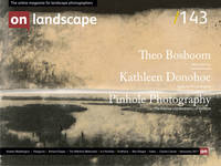
However, this presumes that we have a hole with no width or height. If we introduce a ‘real’ hole, we can see that each ‘point’ in our letter gets ‘blurred’ because light from a single point projects to a circle.
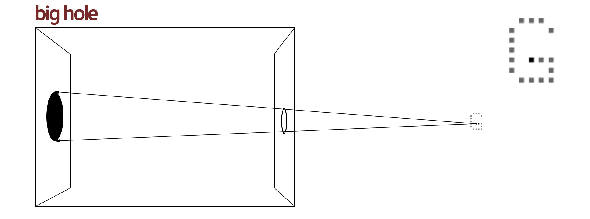
If we make the circle smaller, the amount of blurring gets less and hence the image looks sharper.
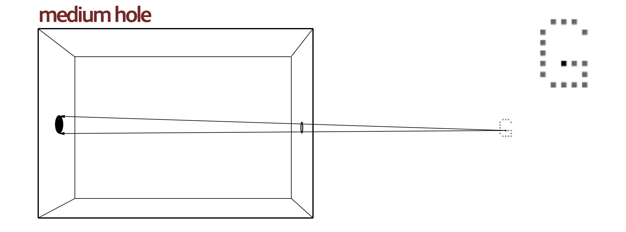
This suggests that if we have a really small hole we get the sharpest image. However, sadly, science gets in the way. When light passes close to an edge, it is ‘bent’ by that edge*. This is called diffraction and is minimal for a large hole where the area of the hole away from an edge is a lot more than the area of the hole near the edge which is subject to diffraction. This means there is a transition point as the hole gets smaller where the image starts to blur again because of this diffraction.
The blurring from diffraction is actually a little more complicated than the simple geometric blurring of a large hole and the image formed is a central blurred spot surrounded by less and less bright ‘rings’ of light. This is called an Airy Disc and I’ve shown this in the diagram above.
*actually it’s a lot more complicated than that but quantum physics and wave/particle duality is a little beyond this article
So getting the sharpest image possible means trying to find the balance between geometric blurring because the hole is too large and diffraction blurring because the hole is too small.
Various scientists and undoubted geniuses have tried to work out what size this ‘perfect pinhole’ should be, most notably Prof. Joseph Petzval, Lord Rayleigh and Prof. Lommel. What is surprising is that they all came out with different answers! This is partly because our understanding of diffraction was still developing during their era but the most complicated problem is that have the highest resolution result and having a sharp picture are two different things. There are two different solutions for optimal pinhole size, larger holes for the best resolution, smaller holes for the best contrast, which is what we need for a picture to look sharp.
Finally, just to confuse matters further, our assumption that a pinhole camera renders everything in front of the camera equally sharp is also incorrect. As you can see from the following diagram, as an object gets closer to the pinhole camera, the blurring gets larger. In order to have sharp images up close, you need to have a smaller hole (but that can mean a softer image in the distance!).
I’ll add an appendix to the end of this article with the maths involved in some of these calculations but I think we need some practical results to look at. Tests Ahoy!!
Testing Pinholes
In order to test some of the topics discussed so far, I realised that I needed to get my hands on some pinholes of various sizes. Luckily, the kindly proprietor of Pinhole Solutions is a reader of the magazine and recognised my name and it was only a couple of days later when I received a set of complementary pin holes from size 0.1, 0.2, 0.3 and 0.5 mm (0.4mm was unavailable at the time).
Also, in order to find out if the quality of pinhole makes a difference (and to get the missing 0.4mm hole), I went back to one of the laboratory suppliers I had used when I was lecturing and ordered a 0.3mm and 0.4mm mounted pinhole (these holes are typically used in collimating beams of various sorts).
Untitled 22.tif
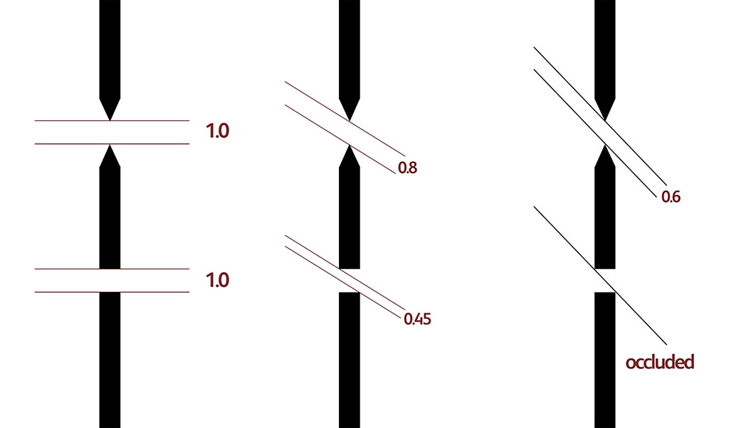
These pinholes are not only very accurately made (using high-intensity particle beams) but they are also made using a very a very thin support material that is tapered to almost nothing near the edge hole. To see why this makes a difference, have a look at the following diagram. You can see that the thick material shows less of a hole when light arrives at more acute angles and is completely blocked well before the thin hole making the vignetting greater and the image circle smaller. These holes are also pretty expensive too at £55 each!
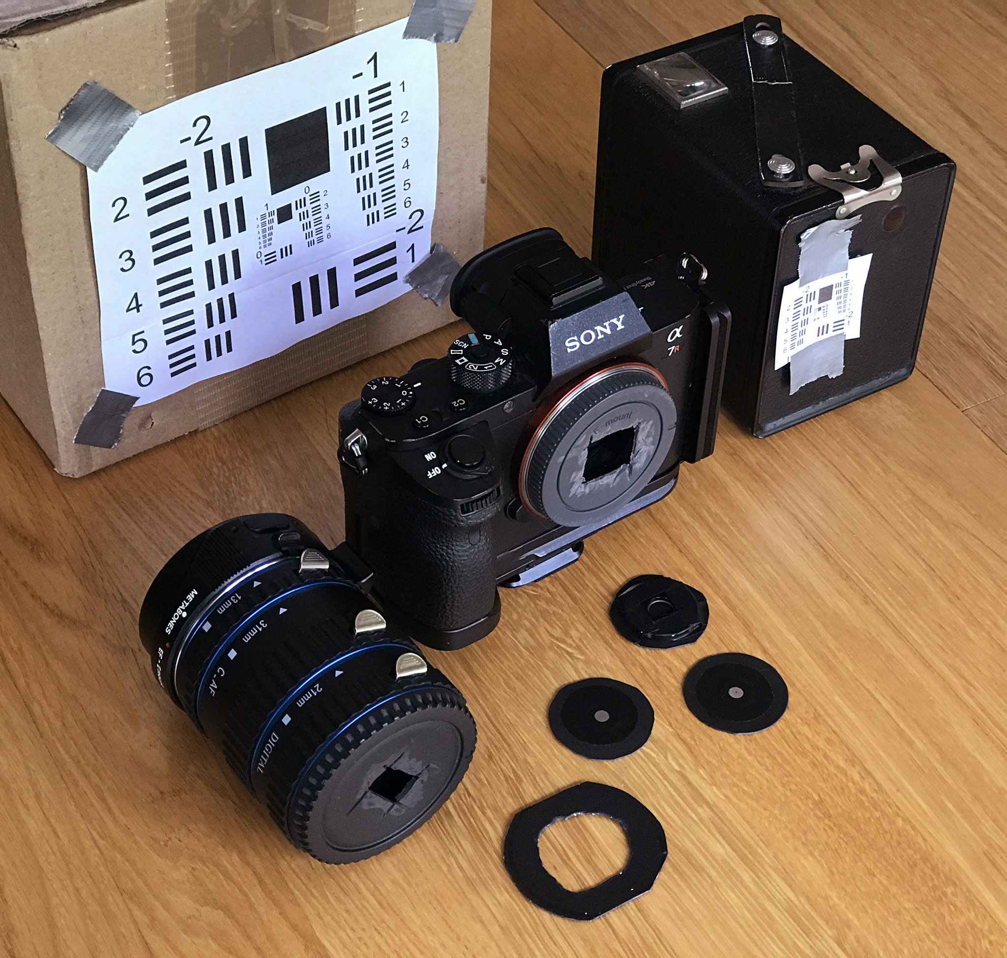
In order to carry out the tests, I modified a Sony E-mount body cap so that I could tape each size hole to the end of the camera. I also used a set of extension tubes, Canon fit tubes on a Metabones Sony to Canon adapter, and a Canon body cap to allow different focal lengths to be tested (25mm, 65mm and 117mm). I then printed out some USAF resolution targets and positioned them at 15cm, 30cm, 60cm, 120cm and 240cm from the pinhole position. Here’s a photograph of the equipment used (I also had three other different size USAF res targets printed).
Here is a comparison of the different pinhole results at the 25mm focal length and 120cm distance.
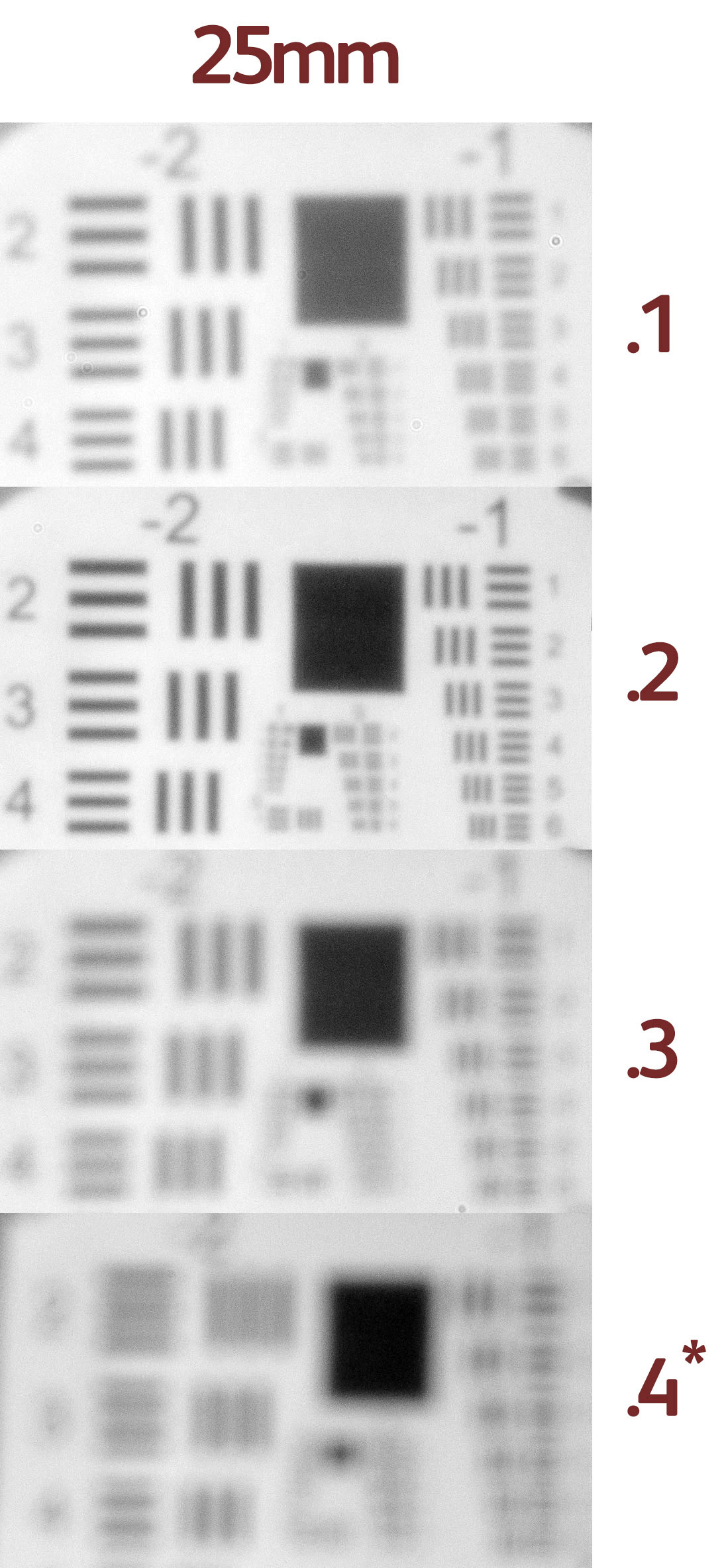
As you can see, for this focal length the 0.2mm hole is obviously the sharpest. The 0.1 is soft and low contrast and the 0.3 and 0.4 are showing spurious resolution (in some cases it’s showing two lines when there are actually three).
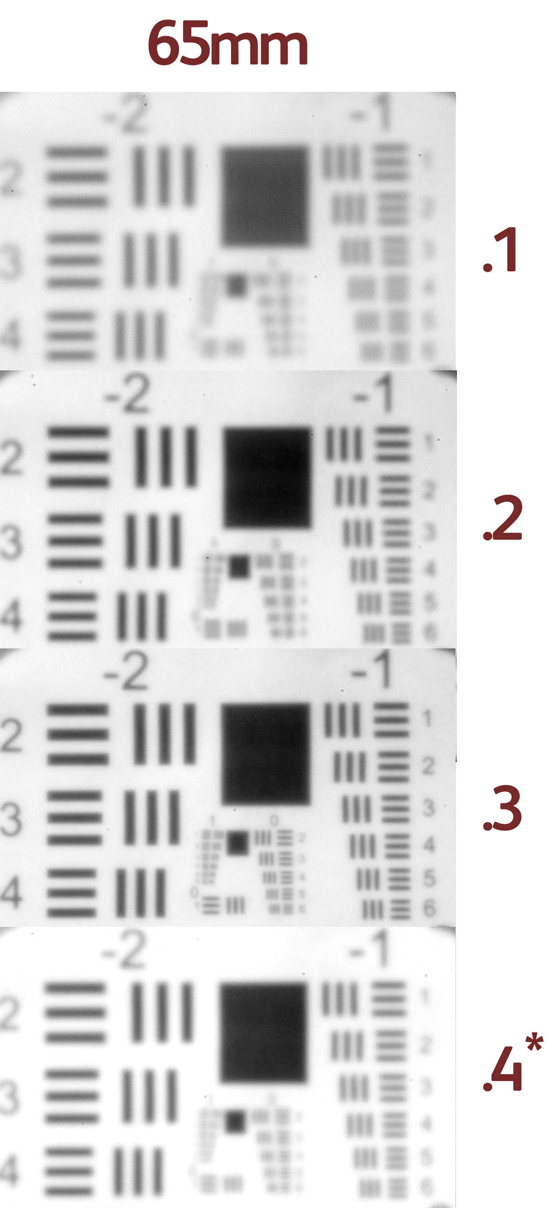
The 65mm focal length shows similar results but this time with 0.3mm being the sharpest result.
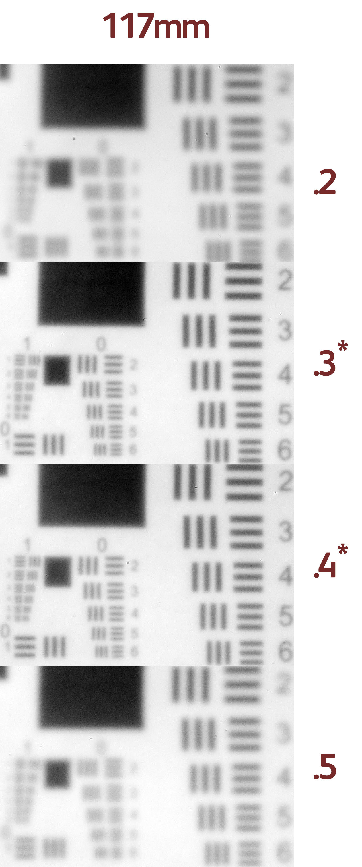
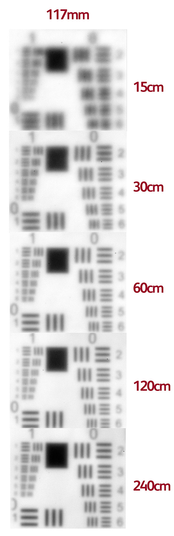
Finally, the 117mm focal length shows the most interesting results. For this example, we can see that the 0.4mm focal length looks the sharpest but if you look closely at the 0.5mm hole, you can see that it is actually resolving smaller sets of lines but generally the whole thing looks very soft.
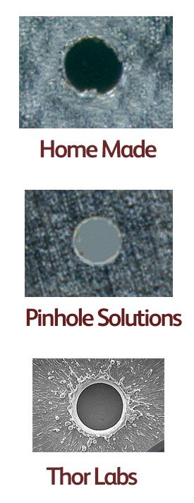
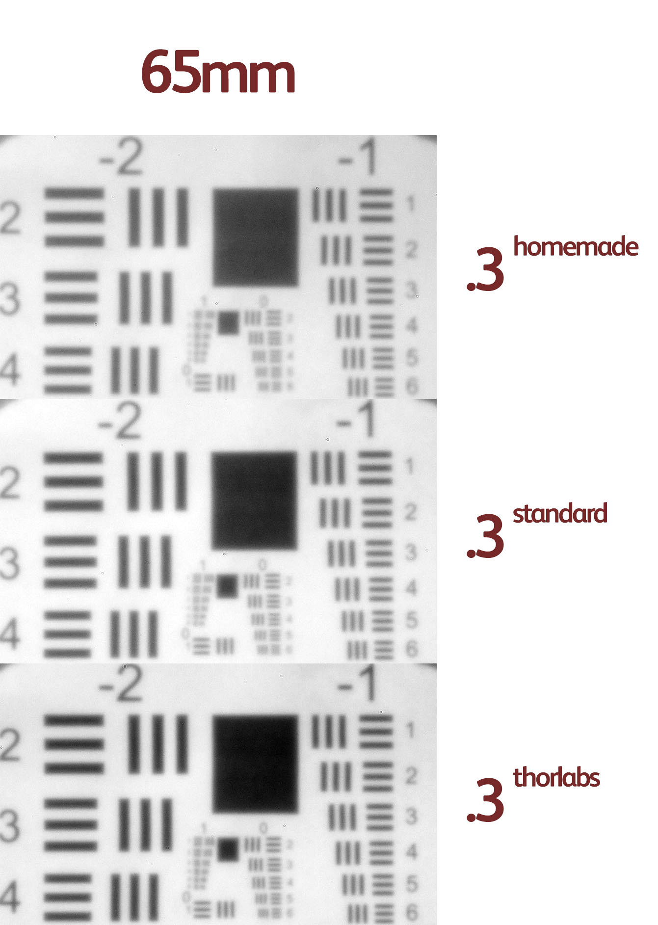
One thing to be aware of is that if there is a star next to the image hole size in these diagrams, the pinhole used is the Thor Labs one. Looking at the results from our Pinhole Solutions hole, our homemade hole (using a pin and sanding down the edges) and the Thor Labs hole, you can see that the biggest variation is in the contrast of the results. It looks like the Thor Labs hole has such as smooth edge to the whole that it avoids spurious diffraction. (I also made some intentionally 'bad' holes by just poking through tin foil and they also showed odd double edges and different resolution in different axes).
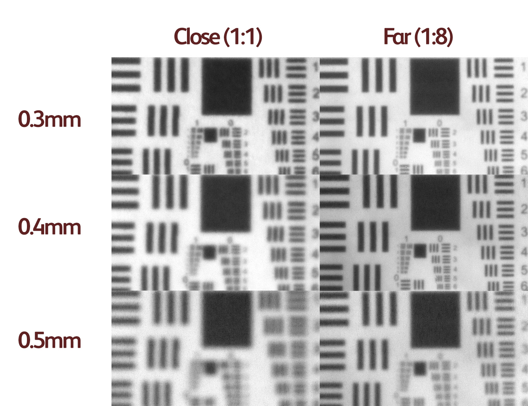
The other experiment was to assess how the sharpness and contrast varied with distance from the pinhole. In the next diagram, you can see the difference between a 1:1 image (distance = focal length) and a 1:8 image (distance = 8x focal length) for different pinhole sizes. You can just about see that although the sharpest 0.4mm hole focusses well at a distance, it is blurry at 1:1. The 0.3mm hole focusses better up close but sacrifices detail at a distance.
You can see this effect a lot more clearly in the following real photograph.
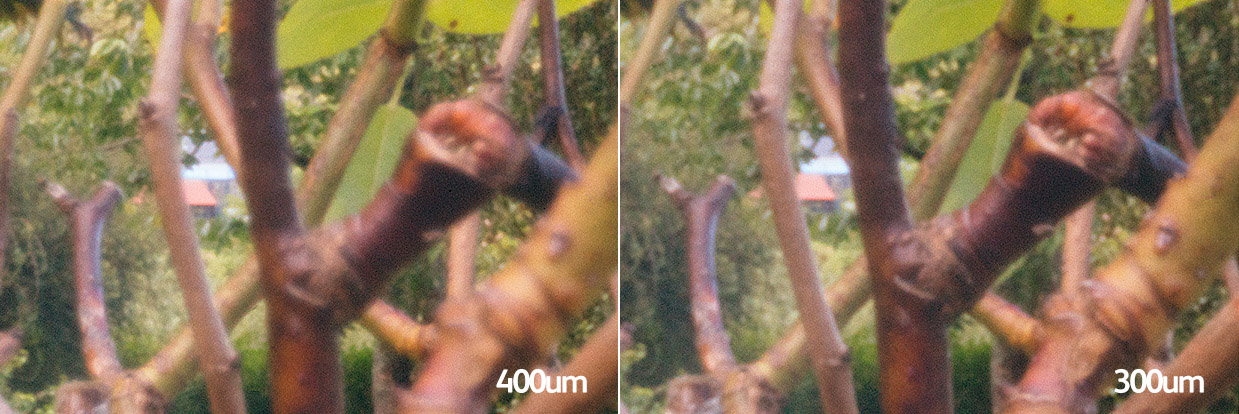
On the left, you can see the ‘optimum’ sharpness pinhole which shows a ‘sharp’ background. On the right, you can see that with a slightly smaller pinhole (25% smaller) the foreground has snapped into focus with only a slight sacrifice in the sharpness of the background. It turns out that the optimum pinhole is worked out for infinity focus which is roughly defined by any distance beyond about 20x the focal length. For our example with a 117mm focal length, this is anywhere from roughly 2m onwards. Anywhere closer than 2m will get a bit softer. In our tests, we noticed the softening for items closer than one meter (or about 10x focal length).
The problem is, most of us don’t have a second pinhole we can substitute into the camera. However, some of us have cameras that can be focussed by changing the distance from film to ‘lens’ e.g. a large format camera.
So we have an alternative trick for closer focus. If we extend the focal length a bit, we should really increase the size of the pinhole. If we don’t increase it, then we have an undersized pinhole which is just what we want in order to be able to focus closer! The book “Way Beyond Monochrome” (highly recommended!!) has a chapter that goes into a few issues we’ve discussed here and they suggest extending the focal length by 50% which will make a position 3x the focal length the sharpest region. Hence for a 25mm focal length (typical for medium format) we would extend the focal length to 37.5mm and the sharpest area would be at 75mm distance.
Conclusions
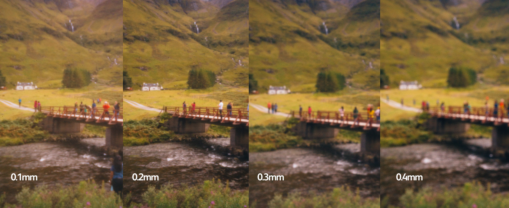
Well, what have we learned from all of this? Firstly it’s pretty obvious that there isn’t really a definitive ‘best’ pinhole size. There are various sizes that are useful for different results. We thought it would be good to show the photographic variations with pinhole size so we took a few photographs. The first shows the variation when using a 25mm focal length where the 0.2mm is the clearest.
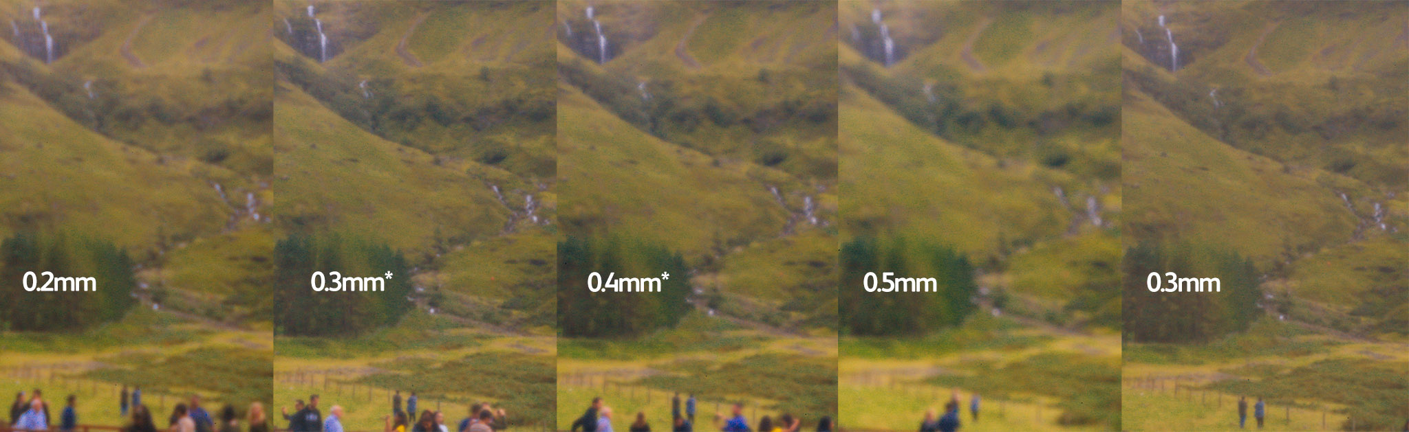
And a 65mm scene (note that we’ve used the Thor Labs pinhole in most examples but here we’ve included the Pinhole Solutions example at the far right which shows a little less contrast). Here the 0.3 is the most contrasty. The 0.4 has a little more fine detail but at a big sacrifice in contrast.
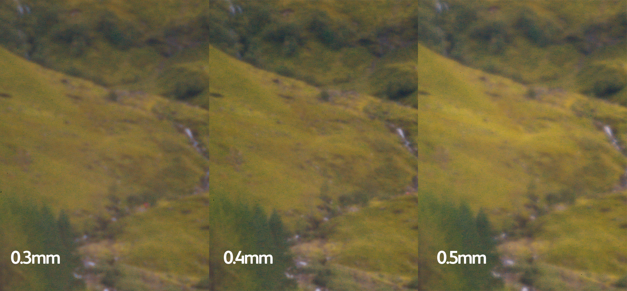
And finally, a 117mm scene where it is very clear that the 0.4mm pinhole is the clearest.
Using the criteria above, it is recommended that you use a pinhole size which is approximately 1.56 x Sqrt( F * wavelength) so for daylight, it simplifies to 0.036 x Sqrt(Focal Length). This 1.56 figure is fairly widely accepted as the best trade off between resolution and contrast.
For our 25, 65 and 117mm focal lengths this gives 0.18mm, 0.3mm and 0.4mm (which we confirmed with our visual results).
Appendix A
People have been making sharp pinhole images for well over a hundred years. A great example is George Davison’s “An Old Farmstead (The Onion Field)”.
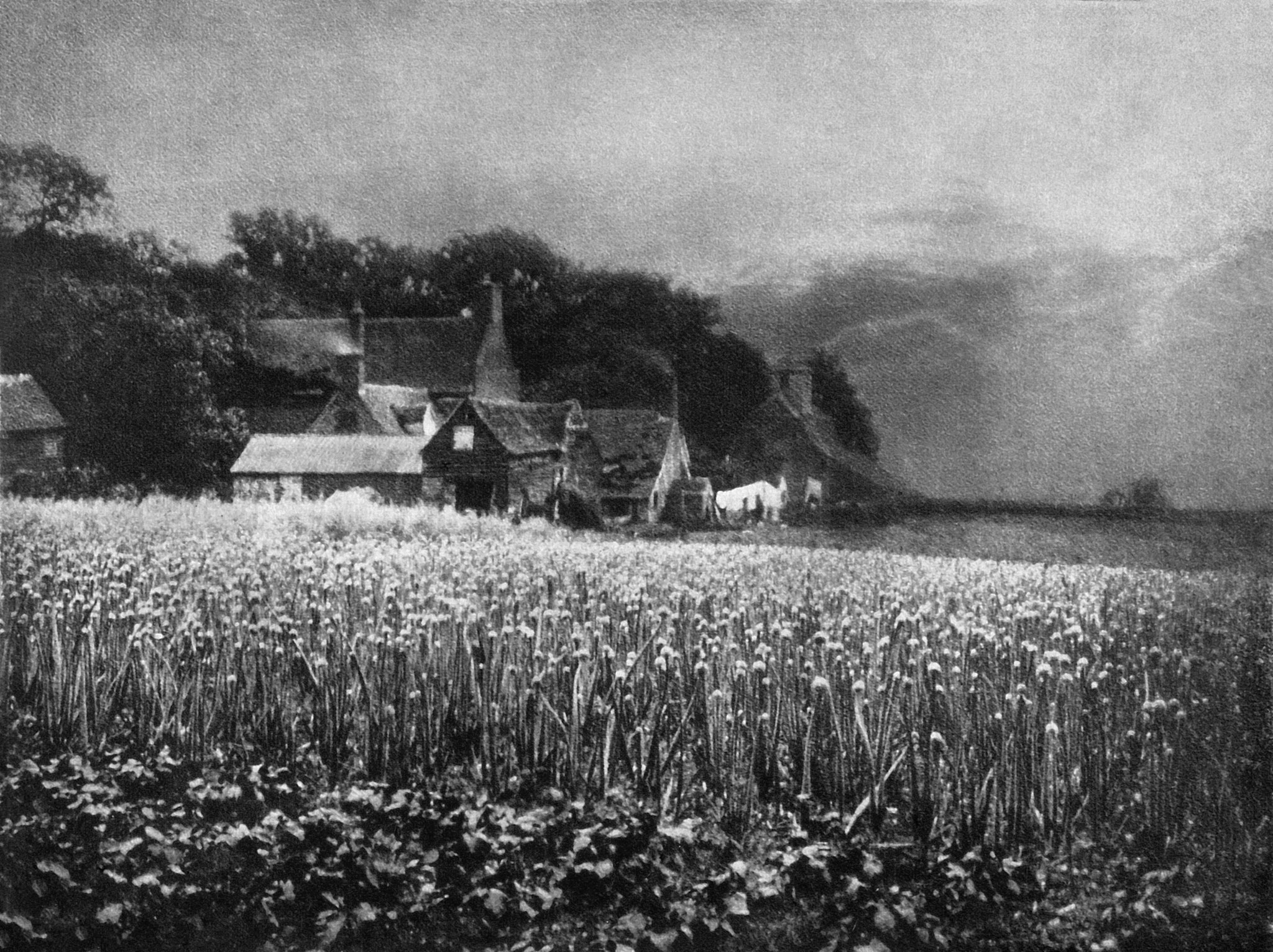
The photograph won the Photographic Society of Great Britain’s annual exhibition and caused a schism between the straight photographers and the pictorial photographers, so much so that George led a group of photographers to form the Linked Ring society. Read more about it here.
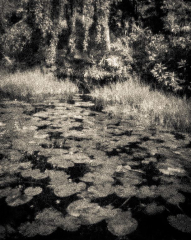
Gallery
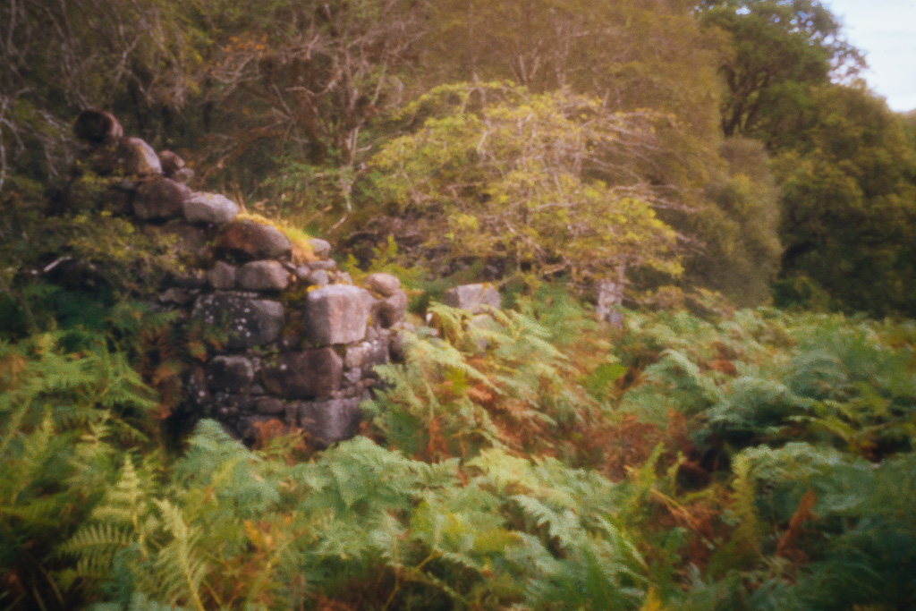
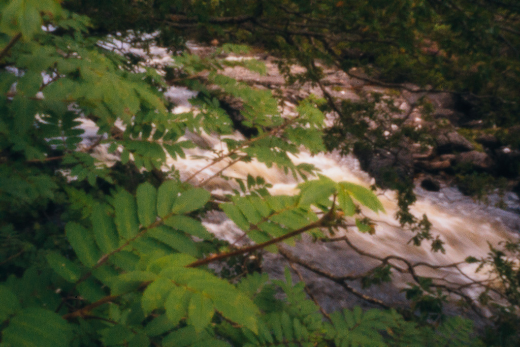
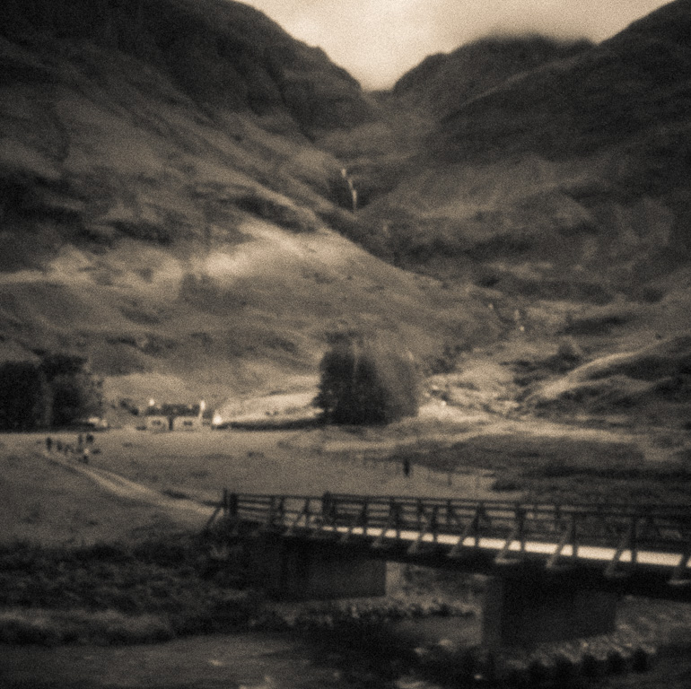
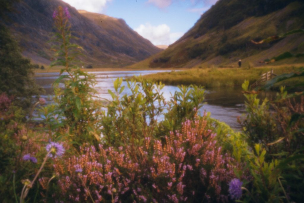
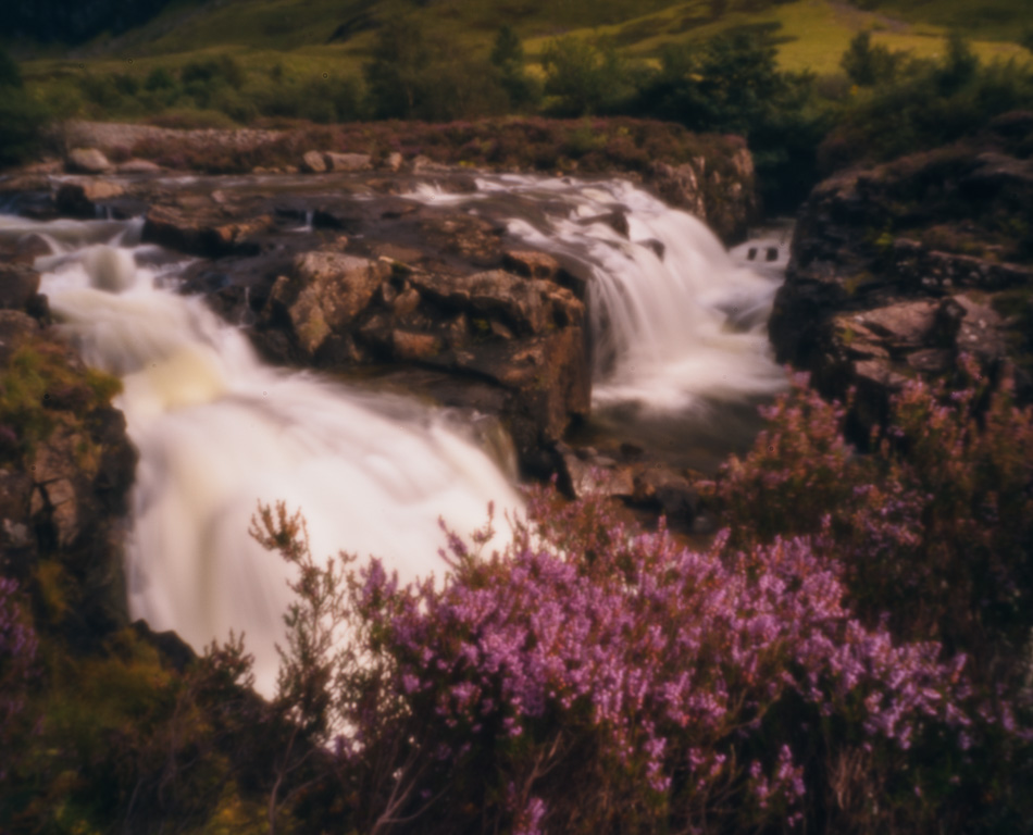
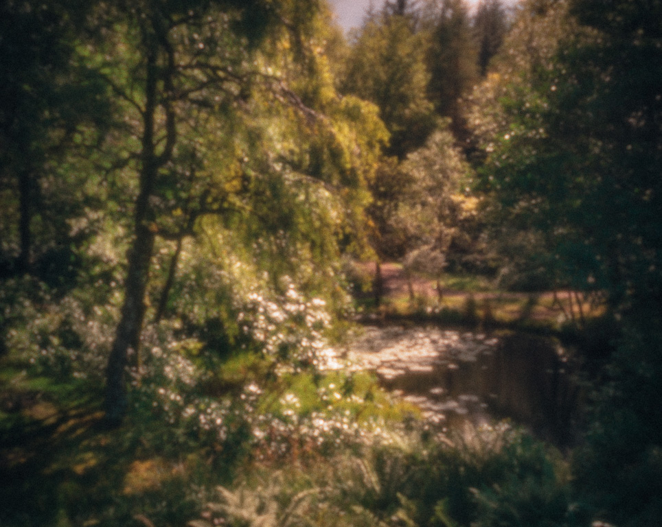
Here is a gallery of 25mm and 15mm photographs taken with the A7Rii and body cap pinhole lens (0.2mm and 0.1mm pinholes) taking during testing.
pinhole photography - other articles to read:
In Praise of Film Pinhole Photography - David O'Brien
Paul Mitchell - Featured Photographer
Lensless Landscapes – Steve Gosling - Book Review